⟵ 11 The Pillars of Water Treatment · Contents · 11 The Pillars of Water Treatment (Engineering Notes) ⟶
The Pillars of Water Treatment: Narrative
From Parts to Patterns
Most people enter water treatment by learning fragments.
We memorize scale inhibitor dosages. We learn how to adjust pump strokes. We are taught what “high cycles” means in a cooling tower. We navigate corrosion coupons, drifting controllers, blowdown valves, biocide rotations, and the 2 a.m. panic that comes when a chiller shuts down and operations wants answers immediately.
There is, admittedly, an endless amount to learn.
But the goal is to move past fragments – because the systems we treat are not governed by isolated numbers on a service report. They are networks of movement: water entering, heat leaving, solids concentrating, gas escaping, chemistry reacting, biology adapting, metal dissolving. Problems do not appear because a single number drifted. They appear because the balance of the system changed.
When iron rises, metal is corroding somewhere or the makeup has changed. When pH falls, acidity is being introduced or buffers are being consumed. When solids increase, they are entering, being generated, or failing to leave. Water does not make these decisions on its own. There’s no mysterious force driving it. The foundations of water treatment have been paved for generations, and they are built upon immutable physical laws. Certain problems may obscure themselves from clear mechanical motives, but they emerge from the same underlying consistency that governs all natural systems.
The Four Pillars give us the recurring failure modes.
Mass Balance gives us an accounting system.
Free Body Diagrams are the field tool that put both to work.
The Four Pillars
Every industrial water system lives under the influence of four recurring forces. They are always present. They never sleep. And they do not negotiate.
Together, they form the Four Pillars of Water Treatment.
Corrosion: The Thief
Corrosion is the slow theft of metal - electrochemistry converting engineered strength back into oxides. It begins quietly, often beneath films and deposits, and it feels sudden only when the system finally fails.
Scale: The Insulator
Scale is dissolved minerals returning to solids. It rarely announces itself loudly, but whispers through rising approach temperatures, declining capacity, and equipment that runs worse for no obvious reason.
Microbiological Growth: The Living Threat
Biology is water inviting life inside. It builds shelter, alters local chemistry, consumes oxidants, and persists because living systems adapt under pressure.
Suspended Solids: The Amplifier
Suspended solids rarely cause failure by themselves. They amplify everything else. They steal access to surfaces, shelter biology, create oxygen differentials, seed deposits, and turn manageable chemistry into localized damage.
You’ve already met each pillar in isolation. This chapter is about what happens when they collide - and how to think clearly when they do.
Connected Failure Modes
The pillars are not separate boxes. They are coupled by physical, chemical, and biological pathways that run in both directions. When you understand those couplings, symptoms begin to sort themselves into causes.
Scale and Corrosion
A thin, adherent mineral film can sometimes reduce direct metal exposure and limit corrosion. A thick, insulating scale deposit does the opposite – it creates hot spots, concentrates chemistry, and builds occluded zones where oxygen availability changes from one location to another. That is fertile ground for localized corrosion.
Corrosion also feeds scale. Iron oxides and roughened surfaces provide excellent nucleation sites for mineral precipitation. The result is a feedback loop: scale deposits promote corrosion, corrosion products promote more deposition.
Biology and Corrosion
Biofilms are not passive slime. They are organized shelter. They create anaerobic microenvironments, trap nutrients, and allow organisms such as sulfate-reducing bacteria to generate corrosive byproducts. That is one path into microbiologically influenced corrosion.
Corrosion products return the favor. Tubercles and roughened surfaces provide structure, protection, and attachment points. A corroded surface is easier to colonize than a clean one.
Biology and Scale
Biofilm changes the surface. It insulates heat transfer, alters local pH and chemistry, and traps ions in extracellular polymeric substance. Those local changes can push a surface toward precipitation even when the bulk water looks manageable.
Scale returns the favor by providing rigid shelter. Once a hard mineral deposit forms over biological material, oxidants struggle to reach what is underneath.
Solids and Everything
Suspended solids are the universal amplifier. They settle in low-flow zones, shield surfaces, intensify oxygen differentials, trap nutrients, and provide a scaffold for both scale and biology. A dirty system makes every other problem easier to start and harder to stop.
That is why “good chemistry” so often fails in dirty equipment. The chemistry may be fine in the bulk water. The surface environment is not.
| CONCEPT LOCK Scale and corrosion are linked through deposits, pH, and thermal stress. Biology and corrosion are linked through MIC, shelter, and corrosion products. Biology and scale share surfaces, insulate heat transfer, and reinforce each other. Suspended solids amplify all three. System cleanliness is the foundation. |
|---|
Mass Balance
A mass balance is the foundation of systems thinking.
It applies the Law of Conservation of Mass to real systems: matter is neither created nor destroyed, only rearranged. It treats the system as a boundary. Across that boundary, mass flows in and mass flows out. Whatever accumulates inside is the difference between the two.
If something is high, it either entered, failed to leave, or changed form inside the boundary. Water has to come from somewhere. Dissolved solids have to come from somewhere. Oxygen has to come from somewhere, and it has to go somewhere too.
Mass balance makes even dynamic systems figure-out-able by forcing four questions:
-
What enters?
-
What leaves?
-
What accumulates?
-
What changes form?
In order to answer these questions, it is common to use a weighted average. When two streams combine, the resulting temperature, conductivity, dissolved oxygen, etc. is the flow-weighted average of the two inputs.
Formula:
Result = (Q₁ × C₁ + Q₂ × C₂) ÷ (Q₁ + Q₂)
Where:
Q = flow rate
C = the property being calculated (temperature, conductivity, DO, etc.)
Free Body Diagrams
A free body diagram puts those questions to work. Its purpose is not to make the system more abstract – it is to make the system traceable.
For any component – condenser tube, tower basin, heat exchanger, branch line, deaerator, boiler drum – the free body diagram asks you to stop staring at the symptom and start accounting for the system.
Example: Boiler Feedwater Conductivity Is High
A fairly standard field complaint goes something like this:
“I don’t know why, but the boiler feedwater conductivity is suddenly high. I’m also not getting any sulfite residual in the boiler. I’ve turned up the pump, but I’m still not getting any.”
This is where we need to shift to system thinking.
Turning up the sulfite pump is a symptom-first reaction. It’s understandable – but it does not address the underlying question: what changed in the balance of the system that made this symptom inevitable?
That is where a free body diagram begins. Not with a lever. With the four questions.
1. What enters the feedwater tank?
In most cases, atmospheric feedwater tanks receive only two meaningful water input streams: makeup water and condensate return. Condensate return typically arrives hot and clean – low dissolved solids, high heat content. Makeup water arrives cold and relatively concentrated – softened to remove hardness, but still carrying dissolved minerals.
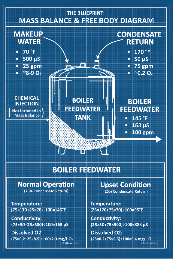
The mixed feedwater conditions are determined by the temperature, conductivity, dissolved oxygen, and flow rate of these two streams. The blueprint for this chapter shows an example of a free body diagram for this theoretical system.
2. What leaves the feedwater tank?
Boiler feedwater exits the tank at a flow rate equal to the combined inputs. It carries the dissolved minerals and heat of the mixed streams into the boiler.
Under normal operation - 75% condensate return - the math is straightforward:
Feedwater Flow: (QCR+QMU) = (75+25) = 100 gpm
Temperature: (QCR×TCR+QMU×TMU)÷QFW = (75×170+25×70)÷100 = 145°F
Conductivity: (QCR×CCR+QMU ×CMU)÷QFW = (75×50+25×500)÷100 = 163 µS
Dissolved oxygen: (QCR×DOCR+QMU×DOMU)÷QFW = (75×0.2+25×8.5)÷100 =~2.3 mg/L
3. What accumulates inside the feedwater tank?
In a properly operating feedwater tank, nothing significant accumulates. There is no evaporative cycling, no further concentration of minerals.
4. What changes form inside the feedwater tank?
Here is part of the answer to the technician’s question. Sulfite fed to the feedwater tank reacts with dissolved oxygen: SO₃²⁻ + ½O₂ → SO₄²⁻. Residual sulfite is consumed in the reaction to produce sulfate. If the oxygen load increases, sulfite demand increases with it – and if the feed rate hasn’t changed, the residual disappears.
Now apply the mass balance to the upset condition – condensate return collapsed to 25%.
Feedwater Flow: (QCR+QMU) = (25+75) = 100 gpm → same flow rate
Temperature: (25 × 170 + 75 × 70) ÷ 100 = 95°F → ∆T = -50°F
Conductivity: (25 × 50 + 75 × 500) ÷ 100 = 388 µS → ∆C = 225 µS
Dissolved oxygen: (25 × 0.2 + 75 × 8.5) ÷ 100 = ~6.4 mg/L → ∆DO = 4.1 mg/L
Under these conditions there is nearly three times the oxygen load on the sulfite program. Conductivity more than doubled. Feedwater temperature dropped 50°F.
The technician wasn’t facing a chemical problem. They were facing a water balance problem that expressed itself as three simultaneously chemical symptoms. The sulfite was doing what it is designed to do, but the conditions changed.
That is the mass balance payoff. The system was figure-out-able from the change in inputs alone – before touching a single chemical feed pump.
The Most Common Diagnostic Error
The most common error in water treatment is not bad chemistry. It is mistaking the signal for the source.
When something is off, there’s a temptation to jump directly into the obvious mechanism: the pump’s not working, the chemical isn’t doing its job, the biocide is old, the controller is wonky, the system’s never run right.
But a cooling tower can develop biofilm because scale allowed it to. A closed loop can corrode because it’s leaking at an expansion tank. A boiler can show high conductivity because condensate return collapsed, and it can test at zero sulfite because the oxygen load tripled.
Symptoms are real, but they’re rarely first.
And this is why the free body diagram matters. It forces you to walk upstream through the facility instead of reacting to the most visible feature. The four pillars are not enemies to be defeated one at a time – they are recurring expressions of broken balance. And broken balance always has a source.
Worked Cascade: pH Drift in a Cooling Tower
Suppose acid feed fails or CO₂ stripping outpaces the control response. The pH rises from 8 to 8.8. That single drift changes several things at once.
Carbonate equilibrium shifts toward CO₃²⁻, increasing calcium carbonate supersaturation. The LSI shifts positive. Scaling pressure on heat-transfer surfaces rises.
General corrosion rates on mild steel decrease – the hydroxide environment favors passive film stability. But if a phosphate-based inhibitor is in use, higher pH increases the risk of calcium phosphate precipitation, fouling surfaces and reducing inhibitor effectiveness.
Biocide efficacy changes too. Free chlorine shifts towards hypochlorite ion - weakening the oxidizing species available for biological control. Biological pressure increases without any change in feed rate.
And as surfaces foul from the increased chemical and biological demands, suspended solids become more likely to accumulate and amplify the cycle further.
What looked like just a pH problem has quickly become a scale problem, a bio-control problem, a solids problem, and potentially an under-deposit corrosion problem if the underlying issue is not managed.
Four simultaneous consequences. All traceable through disciplined system thinking: what entered, what changed form, what accumulated, and how the pillars interacted before the symptoms compounded.
So What Do We Actually Do?
When people ask what I do for a living, I usually hesitate – not because I’m unsure, but because I know what’s coming next.
“I work in industrial water treatment,” I’ll say.
They nod politely. “So… like drinking water?”
Their confusion makes sense. Even my parents aren’t entirely sure what I do. They know it involves chemistry. They know it involves water. They know it sometimes involves boilers or cooling towers. Beyond that, my day to day is an absolute mystery.
Most people never think about cooling unless it fails. Most people never think about steam until it disappears. The systems we protect are invisible by design - buried in mechanical rooms, hidden behind locked doors, running continuously while the building above goes about its business.
But here is what we actually do.
We manage the balance between four forces that are constantly trying to destroy the systems that move heat through the built environment. We keep metal from returning to rust. We keep minerals from returning to stone. We keep organisms from building cities on surfaces that need to stay clean. And we keep dirt from amplifying all of it.
We do this by understanding the physics, chemistry, and biology of water - then tracing what enters, what leaves, what accumulates, and what changes. Only then do we decide where intervention will do the most good.
This is what the previous ten chapters have prepared you for. The chapters that follow will put that discipline into practice.
| CONCEPT LOCK The goal of water treatment is not victory over any single pillar. It is balance. Problems are emergent properties of systems out of balance – not single-variable failures. Trace the mass balance first. Then ask how the pillars are exploiting the imbalance. |
|---|
⟵ 11 The Pillars of Water Treatment · Contents · 11 The Pillars of Water Treatment (Engineering Notes) ⟶