⟵ 12 Cooling Things Down · Contents · 12 Cooling Things Down (Engineering Notes) ⟶
Cooling Things Down: Narrative
The Problem of Heat
Heating things up is easy. Cooling them down is an art.
The core problem is that heat is intangible: it is the internal energy of matter itself. Heat is not something you can scoop up and throw away, just as “cool” is not something that can be added.
This becomes the central problem in cooling:
We can’t actually “cool things down,” we can only relocate heat.
In the Hero of Heat Transfer Chapter, we explored why water is so remarkably suited for this task. Its high specific heat allows it to absorb large amounts of sensible heat with only modest temperature rise. Its high latent heat of vaporization lets it reject enormous quantities of energy when only a small fraction changes phases. These two properties make water the working backbone of industrial cooling.
Moving Heat
At its core, cooling relies on phase transitions - either of water or of a refrigerant.
In the arid Southwest, many homes use evaporative “swamp coolers” for cooling. Hot outside air passes across the wet fill media, transferring sensible heat out of the air and into the water. As the water is recirculated over the fill media, evaporation removes latent heat energy from the bulk water. This cools the recirculating water, allowing the system to continuously remove heat from the outside air. The process is simple, elegant, and effective - when the air is dry.
In more humid climates, evaporative cooling does not work as well. The relative humidity in the surrounding air limits the evaporative efficiency of these units, which limits the amount of heat removal.
Air conditioners solve this problem with a closed refrigerant loop, which removes heat from the indoor air and rejects it outdoors. The refrigerant absorbs heat from the incoming air as it evaporates inside the fan coils. It then rejects the heat at the AC unit and condenses back into a usable liquid. The refrigerant loop is a closed system, but it still relies on latent heat.
These two household systems quietly demonstrate the two halves of industrial cooling:
A swamp cooler is a tiny cooling tower.
A home air conditioner is a very small air-cooled chiller.
For small buildings, these approaches work well. A window unit or a rooftop air conditioner can handle the load with margin to spare. If efficiency slips, comfort degrades slowly. Energy use creeps up. Life goes on.
Industrial systems operate on the same principles, but at a scale where the choice of transport medium becomes decisive.
The Scale of the Problem
At some point, cooling stops being a comfort decision and becomes a structural requirement.
A hospital cannot allow surgical suites to warm up. A data center cannot tolerate a five-degree rise in server inlet temperature. A semiconductor fabrication facility requires cooling water within fractions of a degree, continuously, for months at a time. A pharmaceutical plant cannot let a reactor run hot without destroying the product inside it.
These are not preferences. They are operational constraints.
The cooling loads involved are enormous. We measure them in tons of refrigeration - a unit that originated in the ice-making industry, where cooling capacity was defined by the amount of ice a machine could freeze in a day. One ton of refrigeration represents 12,000 BTU per hour of continuous heat removal.
A large office building might require 500 to 2,000 tons. A hospital campus, 3,000 to 5,000. A data center, 5,000 to 20,000 or more. A petrochemical refinery can demand cooling measured in the tens of thousands of tons.
At these scales, distributed air conditioning - the kind that works perfectly well in a house - collapses. Ductwork grows massive. Fan energy explodes. Redundancy becomes impossible. Maintenance becomes a nightmare of scattered rooftop units, each with its own refrigerant charge, its own filter, its own failure mode.
Multiple factors determine the breaking point - load size, building size, operating hours, layout, maintenance staff. As a practical rule of thumb, once you’re in the Costco-sized building class (~150,000 sq ft), you’re often in the range where centralized chilled water starts to make sense.
Beyond a certain size, the logic shifts decisively: you stop trying to move cool air to the problem, and you start moving cool water.
When Chillers Become Inevitable
Once cooling demand becomes large enough, moving cold air stops making sense.
Air is a terrible medium for moving heat. It has a specific heat of roughly 0.24 BTU/lb·°F - less than a quarter of water. Air is also roughly 800 times less dense than water at standard conditions. To move the same amount of heat, you would need to push vastly more volume of air through vastly larger ducts with vastly more powerful fans.
Water moves heat with extraordinary efficiency through small pipes. A six-inch chilled water pipe can carry as much cooling capacity as a four-foot air duct. The pumping energy is a fraction of the fan energy. The piping is compact, durable, and easy to insulate. Redundancy is simple: install a second chiller and a set of valves.
This is why every large cooling system converges on the same architecture. A chiller produces chilled water. That chilled water is pumped to wherever cooling is needed - air handlers, fan coils, process heat exchangers. The water absorbs heat, returns to the chiller, and is cooled again.
The chiller does not cool the building directly. It produces a cold fluid that does the work on its behalf.
Understanding what happens inside the chiller - and why it needs a cooling tower to survive - is the foundation of everything we do in open recirculating water treatment.
| CONCEPT LOCK Chillers exist because water moves heat far more efficiently than air. The chiller produces chilled water. The building consumes it. Once chilled water enters the picture, water treatment becomes unavoidable. |
|---|
What a Chiller Actually Does
A chiller is a heat pump dedicated to cooling.
It moves heat from a chilled-water loop into a condenser-water loop using a refrigerant cycle. The chiller does not create cold. It relocates heat - lifting it from a low temperature where it causes problems to a higher temperature where it can be rejected.
To understand how, we must first return to refrigerants.
In the Hero of Heat Transfer, we explored why water resists phase change so stubbornly. Its hydrogen bonds create an enormous energetic barrier: roughly 970 BTU per pound must be invested to transform liquid water into steam.
Refrigerants are the opposite.
They are molecules held together by weak intermolecular forces - London dispersion forces rather than hydrogen bonds. They require far less energy to vaporize and condense, and they do so at temperatures far below water’s boiling point.
R-134a boils at –15°F (–26°C).
Ammonia boils at –28°F (–33°C).
This is why we described refrigerants as “quitters by design.” Their willingness to change phase at low temperatures is precisely what makes refrigeration possible. They absorb heat by evaporating at a useful temperature, and they release it by condensing at a slightly higher one.
This all relies on a secondary lever: pressure.
Lowering pressure lowers the boiling point. Raising pressure raises the condensation point. By compressing and expanding a refrigerant, we choose the temperatures at which it absorbs and releases heat through phase changes. This gives us control over a process that thermodynamics would otherwise forbid: moving heat from cold to hot.
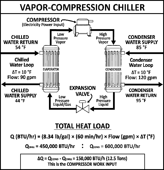
The Four Components of a Chiller
A chiller accomplishes this with four components, each playing a distinct role in the refrigerant cycle.
Evaporator (Chilled Water Side)
The evaporator is a heat exchanger where the refrigerant absorbs heat from the chilled water loop. The refrigerant enters as a cold, low-pressure liquid. Inside the evaporator, pressure is kept low enough that the refrigerant boils at approximately 38–42°F. As it evaporates, it absorbs latent heat from the chilled water flowing over the tubes. The chilled water transfers the building heat into the refrigerant and leaves cold - typically 42–44°F - where it is pumped back into the building.
This is where the chiller does its job. Everything else exists to reset the refrigerant so it can do this again.
Compressor
The compressor takes the low-pressure refrigerant vapor exiting the evaporator and squeezes it. Compression raises both the pressure and the temperature of the vapor, transforming it into a superheated, high-pressure gas. This is the primary energy input to the system - the electricity that powers the chiller. The compressor is doing the thermodynamic work of lifting heat from a low temperature to a higher one.
Condenser (Cooling Tower Side)
The condenser is a heat exchanger where the refrigerant releases the heat it absorbed in the evaporator plus the heat added by compression. At the elevated pressure created by the compressor, the refrigerant condenses at roughly 100–120°F. As it condenses, its latent heat is released into the condenser water flowing over the tubes. The condenser water absorbs this heat and carries it away.
This is the critical handoff. The heat that was in the building is now in the condenser water.
Expansion Valve
The expansion valve throttles the high-pressure liquid refrigerant to a lower pressure liquid/vapor. This pressure drop causes part of the refrigerant to flash and lowers its saturation temperature, returning it to a cold, low-pressure state ready to absorb heat again in the evaporator.
The cycle runs continuously. Evaporate. Compress. Condense. Expand. Each revolution moves heat from the chilled water loop into the condenser water loop.
The Cooling Tower: The Chiller’s Exit Strategy
The cooling tower is where the chiller gets to exhale.
Warm condenser water leaves the chiller carrying heat that has been absorbed from the building, lifted by the compressor, and transferred across the condenser tubes.
The cooling tower provides the final release through evaporation.
Warm condenser water is pumped to the top of the cooling tower and distributed across a large surface area of fill media. As air is drawn across the wetted fill, a small fraction of the water evaporates. Each pound of water that transitions from liquid to vapor absorbs roughly 970 BTU of latent heat, cooling the remaining liquid water. The cooled water collects in the basin and is pumped back to the chiller condenser.
The general rule of thumb bears repeating: evaporating 1% of the recirculating water cools the bulk water by approximately 10°F. This is an extraordinary amount of heat rejection accomplished by a very small amount of water loss.
The cooled water collects in the tower basin and is pumped back to the chiller condenser, where it absorbs heat again. The cycle repeats.
When the Cycle Breaks Down
If the condenser cannot transfer heat effectively, the consequences cascade upstream.
Condenser tubes are scaled or fouled → heat transfer is impeded → the temperature difference across the condenser shrinks → the refrigerant cannot condense efficiently → the compressor must work harder to maintain the same pressure differential - a condition called increased lift.
Energy consumption rises. Cooling capacity falls. If the imbalance is severe enough, the chiller protects itself by unloading or shutting down entirely.
The tower does not do the thermodynamic work of the chiller. But the chiller cannot function without the tower’s cooperation.
Every threat we have studied in this book converges at the cooling tower. Scale insulates heat-transfer surfaces and reduces the tower’s ability to wet its fill. Corrosion weakens the structural steel and piping that hold the system together. Biofilm fouls surfaces, restricts heat transfer, creates health hazards, and shelters organisms from biocides. Suspended solids settle in basins and condenser tubes, amplifying everything else.
We do not treat cooling towers because we care about towers.
We treat them because the chiller, the building, and every process downstream depends on the tower doing its job.
| CONCEPT LOCK The cooling tower is the final heat-rejection step in the system. If tower performance degrades, condenser temperature rises and chiller efficiency falls. This is where scale, corrosion, biology, and solids become operationally expensive. |
|---|
The Cooling Tower Mass Balance
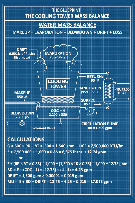
A cooling tower is an open water system. Water enters as makeup. Water leaves as evaporation, blowdown, drift, and leaks. The balance between these flows determines the chemistry, the efficiency, and the cost of the entire operation.
Understanding the mass balance is the foundation of cooling tower management, and must answer each of the four questions:
-
What enters?
-
What leaves?
-
What accumulates?
-
What changes form?
The overall mass balance is simple: what comes in must equal what goes out.
Makeup = Evaporation + Blowdown + Drift + Leaks
Evaporation
Evaporation is the tower’s purpose. It is how the system rejects heat.
We derived this relationship in the Hero of Heat Transfer Chapter – each pound of water that evaporates absorbs approximately 1,000 BTU/lb of latent heat. If the tower must reject a given heat load, a corresponding amount of water must evaporate. The Engineering Notes provide two methods for calculating evaporation rate in the field.
This is the first key idea in the tower mass balance: evaporation is set by load.
Blowdown
Evaporation leaves dissolved minerals behind. As pure water leaves as vapor, the remaining water becomes more concentrated. Calcium rises. Alkalinity rises. Silica rises. Chloride rises. Everything that does not evaporate becomes more crowded, including microbes and suspended solids.
Blowdown is the controlled release of that concentrated water. It is replaced by fresh makeup, which resets the chemistry and prevents the tower from concentrating to the point of scale, corrosion, or severe fouling.
This is the second key idea in the tower mass balance: blowdown is the main controllable loss term.
Drift and Leaks
Drift is the small quantity of liquid water that escapes the tower as fine droplets carried by the exhaust air. Modern drift eliminators reduce this loss to roughly 0.001–0.006% of the recirculation rate. It is typically a minor term in the water balance, but it is not zero.
Leaks are unpredictable but must be accounted for. Both drift and leaks represent unmetered water leaving the system. They carry the full concentration of the tower water with them – unlike evaporation, which leaves pure water and concentrates what remains.
This is the third key idea in the tower mass balance: unmetered losses act as uncontrolled blowdown, and they change the mass balance.
Makeup
Makeup is the fresh water added to replace everything the tower loses:
Makeup = Evaporation + Blowdown + Drift + Leaks
Every gallon of water the tower consumes traces back to these four terms.
Cycles of Concentration
So far we have accounted for what enters and what leaves the cooling tower. The mass balance still requires us to address what accumulates and what changes form.
Pure water exits through evaporation, leaving dissolved solids behind in the bulk water. The solids accumulate. This accumulation is measured by cycles of concentration (COC) – the ratio of dissolved solids in the tower water to dissolved solids in the makeup.
COC is the single most important variable governing water usage, chemical consumption, and scaling risk in an open recirculating system. We introduced it in the Scale chapter as a measure of how crowded the solution has become. Here, it becomes the operational control point for the entire mass balance.
The relationship between cycles and blowdown follows a curve of diminishing returns. Moving from 2 cycles to 3 cycles cuts blowdown in half. Moving from 3 to 4 cuts it again, but by only 33%. Moving from 4 to 5 saves 25% more. The biggest gains come from the first improvements. After roughly 6 cycles, the water savings flatten.
But the risk does not flatten.
Each additional cycle multiplies every dissolved species in the water. Calcium, alkalinity, silica, sulfate, chloride - they all climb in lockstep. The scaling indices worsen. The demand on inhibitors increases. This is the fundamental tradeoff of cooling tower management: water efficiency versus chemical risk.
The Engineering Notes derive the exact relationships between evaporation, blowdown, makeup, and cycles, and include a water savings table that shows the diminishing returns in hard numbers.
When the Balance Lies
In practice, COC is usually estimated with conductivity. This works because most dissolved solids contribute to conductivity, making it a practical real-time surrogate for concentration. But it is not a perfect representation.
Conductivity can tell you that the water is concentrating, but it does not account for transformation within the system. This brings us to the final mass balance question: what changes form?
Past a mineral’s solubility limit, scale and deposition begin to occur. When calcium carbonate precipitates out of solution, its contribution to conductivity disappears, but the system does not know the difference. Makeup water continues to enter. The conductivity controller continues to hold its setpoint. The system makes up the shortfall – and the true concentration of scaling species drifts away from what conductivity reports.
This is why the best practice is to compare the COC between a soluble tracer ion - one that does not scale or deposit – against a scaling-risk ion. Chloride is often used as the standard tracer. Calcium is often the standard scaling indicator. If the chloride-based COC and the calcium-based COC diverge significantly, minerals are leaving the mass balance as scale.
This comparison is a diagnostic tool, not a routine measurement. But it is the only way to verify that the mass balance is truly in balance – that what we think is accumulating in solution has not quietly changed form and left the water as a deposit on a surface.
| CONCEPT LOCK Evaporation is fixed by the heat load. It cannot be reduced without reducing the load. Blowdown is controlled by cycles. Higher cycles mean less blowdown. The mass balance must address what accumulates and what changes form. |
|---|
Why Every Gallon Matters
When I present water usage data to facility managers, the most common reaction is disbelief.
A 1,000-ton chiller plant rejects roughly 15,000,000 BTU/hr to the cooling tower (the building’s heat load plus the heat generated by the compressor). That requires approximately 30 gallons per minute of evaporation – disappearing into the atmosphere, every minute the system runs. Over a six-month cooling season averaging 12 hours of full-load cooling per day, a single plant can evaporate nearly 3.9 million gallons of water.
This is the cost of rejecting heat. We cannot avoid it.
But the total water consumed by the tower is evaporation plus blowdown plus drift. Drift should be negligible, and blowdown is entirely within our control.
At 3 cycles of concentration, blowdown adds roughly 1.95 million gallons. At 6 cycles, it drops to about 0.78 million gallons of water. The difference between operating at 3 cycles and 6 cycles for this single cooling tower is almost 1.2 million gallons of water per cooling season.
In regions where water is scarce or expensive - and increasingly, both - that difference is not trivial.
This is why cycles of concentration are not just a chemistry variable. They are a resource variable. Every cycle we gain reduces the total water footprint of the building. Every cycle we lose wastes water that, in many regions, comes from largely non-renewable groundwater.
Protecting water is not separate from managing chemistry. It is the same job.
The engineering notes will give you the tools to do it.
The Complete Picture of Cooling
The cooling system is a chain. Every link depends on the others.
The building generates heat. The chilled water loop absorbs it. The chiller lifts it from the chilled water loop into the condenser water loop. The cooling tower rejects it to the atmosphere through evaporation.
We do not treat any single component. We manage the conditions that allow the chain to function.
Scale on condenser tubes reduces heat transfer, forcing the compressor to work harder and consuming more energy. Corrosion in the tower weakens structural members and creates iron deposits that foul surfaces and harbor biology. Biofilm on fill media restricts airflow and reduces evaporative efficiency. Suspended solids settle in basins, clog nozzles, and create the stagnant conditions where all three problems accelerate.
The job of the water treater is to hold them in balance.
This is the art of cooling things down.
It begins with understanding that heat is intangible and must be moved. It continues with understanding that chillers are the most efficient machines we have for moving it. And it culminates in understanding that the cooling tower - the open, exposed, chemically hostile system at the end of the chain - is where our expertise matters most.
| CONCEPT LOCK The cooling system is a chain: building → chilled water → chiller → condenser water → cooling tower → atmosphere. Every pillar converges within the condenser and the tower. Scale insulates. Corrosion weakens. Biology fouls. Solids amplify. The water treater’s job is balance: maximize cycles, protect surfaces, conserve water. |
|---|
⟵ 12 Cooling Things Down · Contents · 12 Cooling Things Down (Engineering Notes) ⟶